Posts

16-to-1 multiplexer (16X1 MUX) Verilog

Image
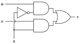
Bottom-UP Hierarchical Structure Structure modeling of 2-to-1 MUX 4-to-1 MUX using two 2-to-1 MUX 8-to-1 MUX using two 4-to-1 MUX 16-to-1 MUX usng two 8-to-1 MUX   1. Structural Modeling of 2-to-1 MUX Design Code _________________________________________________________________________________ module MUX_2X1(input I0, I1, S, output Y);   wire sbar, w1, w2, Y;   not G1 (sbar, S);   and G2 (w1, I0, sbar);   and G3 (w2, I1, S);   or G4 (Y, w1, w2); endmodule _________________________________________________________________________________ Test Bench _________________________________________________________________________________ module MUX_test;  reg [2:0] x;    wire z;   MUX_2X1 M1 (x[0], x[1], x[2], z);    initial      begin           $display("\t\t Time\tSelect  A B \t Z");           $monitor($time,"\t %b \t%b %b \t %b", x[2], x[0], x[1], z);           x = 3'O0;       #5 x = 3'O1;  

MUX Multiplexer Verilog

Image
2x1 Multiplexer For S0 = 0, Z=A For S0 = 1, Z=B Design Code _____________________________________________________________________________ module MUX_2X1(A, B, S0, Z);   input A, B, S0;   output Z;   wire Z;   assign Z = S0 ? B : A; // If S0=0(false), Z=A; If S0 = 1(true), Z=B endmodule ______________________________________________________________________________ Test Bench ______________________________________________________________________________ module MUX_test; reg [2:0] x;   wire z;   MUX_2X1 M1 (x[0], x[1], x[2], z);   initial     begin           $display("\t\t Time\tSelect  A B \t Z");           $monitor($time,"\t %b \t%b %b \t %b", x[2], x[0], x[1], z);           x = 3'O0;       #5 x = 3'O1;       #5 x = 3'O2;       #5 x = 3'O3;       #5 x = 3'O4;       #5 x = 3'O5;       #5 x = 3'O6;       #5 x = 3'O7;       #5 $finish;     end endmodule __________________

Carry Lookahead 4-bit Adder Verilog

Image
Logic Diagram for Sums  Logic Diagram for Carries There are two important variables in Carry lookahead Adder Carry Generate Component Gi: It state that output carry Ci+1 is generated irrespective input carry Ci. This state occurs when both inputs Ai and Bi are 1. so Gi = Ai.Bi Carry Propagate Component Pi: It state that input carry Ci is propagated to output carry Ci+1. In other words, in this state the output carry Ci+1 is equal to input carry Ci. This state occurs when either of input is 1, other is 0. (or One input is compliment of other input). So Pi = Ai^Bi Overall equation for output carry Ci+1 = Gi + Pi.Ci (in other words, Cout = A0.B0 + (A0^B0).Cin) Sum = (Ai^Bi)^Ci = Pi^Ci Design Code _________________________________________________________________________________  module Carry_Lookahead_Adder(a,b,cin,sum,cout);   input[3:0] a,b; input cin;   output [3:0] sum; output cout;   wire p0,p1,p2,p3,g0,g1,g2,g3,c1,c2,c3;   assign p0=(a[0]^b[0]), p1=

N-bit Adder Verilog

Image
N-bit Adder using generate Lets examine the full adder module Full_adder(output S, Cout, input A, B, Cin);   wire w1, w2, w3;    xor G1 (w1, A, B);   xor G2 (S, w1, Cin);   and G3 (w2, A, B);   and G4 (w3, w1, Cin);   or G5 (Cout, w2, w3); endmodule N-bits Adder requires Two N-bits Input variables (A, B) 1-bit Cin One N-bits Output variable (S) 1-bit Cout N-Full Adders and internal mapping ____________________________________________________________________________ //Design Code module Nbit_Adder(S, Cout, A, B, Cin);   parameter N = 8;   input [N-1:0] A, B;   input Cin;   output [N-1:0] S;   output Cout;   wire [N:0] C;   assign C[0] = Cin;   assign Cout = C[N];   genvar i;   generate for (i=0; i<N ; i=i+1)     begin        wire w1, w2, w3;       xor G1 (w1, A[i], B[i]);       xor G2 (S[i], w1, C[i]);       and G3 (w2, A[i], B[i]);       and G4 (w3, w1, C[i]);       or G5 (C[i+1], w2, w3);

8 bit Adder Verilog

Image
Eight bit Adder By cascading of two - 4-bit Adders Design Code _________________________________________________________________________________  module Adder_8bit(input [7:0] A, B, input Cin, output [7:0] S, output Cout);   wire Cout1;   Adder_4bit ADD1 (A[3:0], B[3:0], Cin, S[3:0], Cout1);   Adder_4bit ADD2 (A[7:4], B[7:4], Cout1, S[7:4], Cout); endmodule   module Adder_4bit(input [3:0] A, B, input C0, output [3:0] S, output C4);   wire C1, C2, C3;   Full_adder FA0 (S[0], C1, A[0], B[0], C0);   Full_adder FA1 (S[1], C2, A[1], B[1], C1);   Full_adder FA2 (S[2], C3, A[2], B[2], C2);   Full_adder FA3 (S[3], C4, A[3], B[3], C3); endmodule module Full_adder(output S, C1, input A, B, C0);   wire w1, w2, w3;   Half_Adder HA1 (w1, w2, A, B);   Half_Adder HA2 (S, w3, w1, C0);   or_function G1 (C1, w2, w3); endmodule module Half_Adder(output S, C, input A, B);   xor G1 (S, A, B);   and G2 (C, A, B); endmodule module or_function(output f, input a, b);    o

4-bit Adder verilog

Image
Four bit parallel adder Hierarchical Levels 1. 4 Bit Adder using 4 Full Adders 2. Full Adder using two Half Adders 3. Half Adder using logic gates Structural style (using 4 - full adder) ______________________________________________________________________________ module Adder_4bit(input [3:0] A, B, input C0, output [3:0] S, output C4);   wire C1, C2, C3;   Full_adder FA0 (S[0], C1, A[0], B[0], C0);   Full_adder FA1 (S[1], C2, A[1], B[1], C1);   Full_adder FA2 (S[2], C3, A[2], B[2], C2);   Full_adder FA3 (S[3], C4, A[3], B[3], C3); endmodule module Full_adder(output S, C1, input A, B, C0);   wire w1, w2, w3;   Half_Adder HA1 (w1, w2, A, B);   Half_Adder HA2 (S, w3, w1, C0);   or_function G1 (C1, w2, w3); endmodule module Half_Adder(output S, C, input A, B);   xor G1 (S, A, B);   and G2 (C, A, B); endmodule module or_function(output f, input a, b);    or G1 (f, a, b); endmodule ___________________________________________________________

Full Adder Verilog

Image
Full Adder A. Behavioral Truth Table Using UDP Using Operators Data Flow Using Assign B. Structural Functional level Gate Level 1. Using UDP Design Code ___________________________________________________________________________ primitive FA_sum(sum, a, b, c); input a, b, c; output sum; table      // a b c : Sum         0 0 0 : 0;   0 0 1 : 1;   0 1 0 : 1;   0 1 1 : 0;   1 0 0 : 1;   1 0 1 : 0;   1 1 0 : 0;   1 1 1 : 1; endtable endprimitive primitive FA_carry(cout, a, b, cin); input a, b, cin; output cout; table      // a b c : cout         1 1 ? : 1;  // ? is Don't care   ? 1 1 : 1; // we know that if any two  inputs is high, cout is high   1 ? 1 : 1;   0 0 ? : 0; // we also know that if any two  inputs is low, cout is low   ? 0 0 : 0;   0 ? 0 : 0; endtable endprimitive _________________________________________________________________________________ Test Bench _________________________________