16-to-1 multiplexer (16X1 MUX) Verilog
Bottom-UP Hierarchical Structure
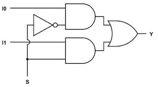
1. Structural Modeling of 2-to-1 MUX
5 0 1 0 1
10 0 0 1 0
15 0 1 1 1
20 1 0 0 0
25 1 1 0 0
30 1 0 1 1
35 1 1 1 1

- Structure modeling of 2-to-1 MUX
- 4-to-1 MUX using two 2-to-1 MUX
- 8-to-1 MUX using two 4-to-1 MUX
- 16-to-1 MUX usng two 8-to-1 MUX

Design Code
_________________________________________________________________________________
module MUX_2X1(input I0, I1, S, output Y);
wire sbar, w1, w2, Y;
not G1 (sbar, S);
and G2 (w1, I0, sbar);
and G3 (w2, I1, S);
or G4 (Y, w1, w2);
endmodule
_________________________________________________________________________________
Test Bench
_________________________________________________________________________________
module MUX_test;
reg [2:0] x;
wire z;
MUX_2X1 M1 (x[0], x[1], x[2], z);
initial
begin
$display("\t\t Time\tSelect A B \t Z");
$monitor($time,"\t %b \t%b %b \t %b", x[2], x[0], x[1], z);
x = 3'O0;
#5 x = 3'O1;
#5 x = 3'O2;
#5 x = 3'O3;
#5 x = 3'O4;
#5 x = 3'O5;
#5 x = 3'O6;
#5 x = 3'O7;
#5 $finish;
end
endmodule
_________________________________________________________________________________
Output
______________________________________________________________
Time Select A B Z
0 0 0 0 05 0 1 0 1
10 0 0 1 0
15 0 1 1 1
20 1 0 0 0
25 1 1 0 0
30 1 0 1 1
35 1 1 1 1
______________________________________________________________
2. Structural Modeling of 4-to-1 MUX

Design Code
_________________________________________________________________________________
// Code your design here
module MUX_4X1(input i0, i1, i2, i3, s0, s1, output Y);
wire Y1, Y2;
MUX_2X1 M1 (i0, i1, s0, Y1);
MUX_2X1 M2 (i2, i3, s0, Y2);
MUX_2X1 M3 (Y1, Y2, s1, Y);
endmodule
module MUX_2X1(input I0, I1, S, output Y);
wire sbar, w1, w2, Y;
not G1 (sbar, S);
and G2 (w1, I0, sbar);
and G3 (w2, I1, S);
or G4 (Y, w1, w2);
endmodule
_________________________________________________________________________________
Test Bench
_________________________________________________________________________________
module MUX_test;
reg [3:0] x;
reg [1:0] s;
wire z;
MUX_4X1 M1 (x[0], x[1], x[2], x[3], s[0], s[1], z);
initial
begin
$display("S1 S0 \t I3 I2 I1 I0 \t Y");
$monitor("%b %b \t %b %b %b %b \t %b", s[1], s[0], x[3], x[2], x[1], x[0], z);
x = 4'h1; s = 2'b00;
#5 x = 4'h2; s = 2'b01;
#5 x = 4'h4; s = 2'b10;
#5 x = 4'h8; s = 2'b11;
#5 x = 4'he; s = 2'b00;
#5 x = 4'hd; s = 2'b01;
#5 x = 4'hb; s = 2'b10;
#5 x = 4'h7; s = 2'b11;
#5 $finish;
end
endmodule
_________________________________________________________________________________
output
__________________________________________
S1 S0 I3 I2 I1 I0 Y
0 0 0 0 0 1 1
0 1 0 0 1 0 1
1 0 0 1 0 0 1
1 1 1 0 0 0 1
0 0 1 1 1 0 0
0 1 1 1 0 1 0
1 0 1 0 1 1 0
1 1 0 1 1 1 0
__________________________________________
3. Structural modeling of 8X1 MUX

Design Code
_________________________________________________________________________________
module MUX_8X1(input [7:0] d, input [2:0] s, output Y);
wire [1:0] y;
MUX_4X1 M1 (d[0], d[1], d[2], d[3], s[0], s[1], y[0]);
MUX_4X1 M2 (d[4], d[5], d[6], d[7], s[0], s[1], y[1]);
MUX_2X1 M3 (y[0], y[1], s[2], Y);
endmodule
module MUX_4X1(input i0, i1, i2, i3, s0, s1, output Y);
wire Y1, Y2;
MUX_2X1 M1 (i0, i1, s0, Y1);
MUX_2X1 M2 (i2, i3, s0, Y2);
MUX_2X1 M3 (Y1, Y2, s1, Y);
endmodule
module MUX_2X1(input I0, I1, S, output Y);
wire sbar, w1, w2, Y;
not G1 (sbar, S);
and G2 (w1, I0, sbar);
and G3 (w2, I1, S);
or G4 (Y, w1, w2);
endmodule
_________________________________________________________________________________
Test Bench
_________________________________________________________________________________
module MUX_test;
reg [7:0] x;
reg [2:0] s;
wire z;
MUX_8X1 M1 (x, s, z);
initial
begin
$display("S2 S1 S0 \t d7 d6 d5 d4 d3 d2 d1 d0 \t Y");
$monitor("%b %b %b \t %b %b %b %b %b %b %b %b \t %b", s[2], s[1], s[0], x[7], x[6], x[5], x[4], x[3], x[2], x[1], x[0], z);
x = 8'h01; s = 3'b000;
#5 x = 8'h02; s = 3'b001;
#5 x = 8'h04; s = 3'b010;
#5 x = 8'h08; s = 3'b011;
#5 x = 8'h10; s = 3'b100;
#5 x = 8'h20; s = 3'b101;
#5 x = 8'h40; s = 3'b110;
#5 x = 8'h80; s = 3'b111;
#5 x = 8'hFe; s = 3'b000;
#5 x = 8'hFd; s = 3'b001;
#5 x = 8'hFb; s = 3'b010;
#5 x = 8'hF7; s = 3'b011;
#5 x = 8'heF; s = 3'b100;
#5 x = 8'hdF; s = 3'b101;
#5 x = 8'hbF; s = 3'b110;
#5 x = 8'h7F; s = 3'b111;
#5 $finish;
end
endmodule
_________________________________________________________________________________
Output
__________________________________________________________________
S2 S1 S0 d7 d6 d5 d4 d3 d2 d1 d0 Y
0 0 0 0 0 0 0 0 0 0 1 1
0 0 1 0 0 0 0 0 0 1 0 1
0 1 0 0 0 0 0 0 1 0 0 1
0 1 1 0 0 0 0 1 0 0 0 1
1 0 0 0 0 0 1 0 0 0 0 1
1 0 1 0 0 1 0 0 0 0 0 1
1 1 0 0 1 0 0 0 0 0 0 1
1 1 1 1 0 0 0 0 0 0 0 1
0 0 0 1 1 1 1 1 1 1 0 0
0 0 1 1 1 1 1 1 1 0 1 0
0 1 0 1 1 1 1 1 0 1 1 0
0 1 1 1 1 1 1 0 1 1 1 0
1 0 0 1 1 1 0 1 1 1 1 0
1 0 1 1 1 0 1 1 1 1 1 0
1 1 0 1 0 1 1 1 1 1 1 0
1 1 1 0 1 1 1 1 1 1 1 0
____________________________________________________________________


Where is the code for 16 to 1 using 8 to 1
ReplyDelete16 to 1 using 4 to1
Delete